Commercial diagnostic applications for Cone Beam Computed Tomography (CBCT) technology first emerged in the early 2000s. Since then, CBCT has revolutionized imaging for medical specialties including dental/maxillofacial, ENT, and breast imaging. CurveBeam AI specializes in CBCT imaging for orthopedics.
Watch to Learn More

WB X-Ray

WEIGHT BEARING CT
TRADITIONAL CT
")
")
")
")

.
About Cone Beam CT
Cone Beam CT images are initially acquired as two-dimensional projections, using a rotating gantry with a fixed-anode X-Ray tube ring, a pulsed X-Ray beam, and a flat panel detector. The gantry rotates 360 degrees and acquires image projections, which are then reconstructed to create a series of axial slices. The term “raw data” refers to projection data, not reconstructed axial slices, which may differ with terminology utilized in conventional medical CT (MDCT).
The osseous (high contrast) details in CBCT datasets should be at par with (or very close to) MDCT. This is the primary diagnostic objective for CBCT scans.
The default reconstructed voxel size from the pedCAT and LineUP systems is 0.37mm or 0.3mm, depending on the protocol selected. The default voxel size for the InReach is 0.2mm. The default voxel size for HiRise system is 0.25mm – 0.3mm.
MDCT employs a narrow, fan shaped beam. Multiple, overlapping rotations are required to capture the region of interest. Tube current (mA) on a MDCT device is adjustable, depending on the region being scanned. Although mA is not the only factor that determines radiation dose, in general, higher mA settings will result in higher radiation dose to the patient. mA settings on MDCT are typically between 50 to 300. Ultra-low-dose settings on MDCT are typically in the range of 20 to 60 mA.
Cone Beam CT employs a wide, cone shaped beam. One rotation captures the region of interest. CurveBeam AI systems have a focused tube current (mA) of 5 – 6.5, which is well below low dose settings of MDCT extremity scans. Image quality of high contrast, hard tissue features is equivalent to MDCT. The flat panel detector is positioned closer to the anatomy being imaged, which means less X-Ray dose is required to capture similar signal strength, as compared to MDCT.

Tradition medical CT Imaging employs a narrow fan beam and detector array

Cone beam CT imaging directs a wide beam on to a flat detector.
SOME DIFFERENCES MAY BE NOTED WHEN COMPARED TO TYPICAL MDCT IMAGES.
 1. Soft tissue detectability is expected to be inferior, although the denser soft tissue structures, as well as the skin surface, can be visualized with good detail.
2. CurveBeam AI systems utilize very low tube current (5 – 6.5mA) which results in reduced radiation dose to the patient. The images will appear noisier, but the trabecular detail is not compromised. However, the tradeoff is well worth it, since the desired diagnostic information is not compromised.
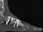
3. The weight-bearing component of the scans, depicting true bio-mechanical alignment of bones under natural load bearing conditions is the most crucual and unique advantage of the WBCT scans.
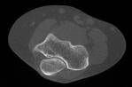
 4. pedCAT datasets may be inferior to MDCT if metal hardware is present in the anatomy.The LineUP and HiRise systems come standard with a Metal Artefact Reduction (MAR) feature. A pedCAT scan with minimal artefact is depicted to the right.
5. Since the X-Ray beam in a CBCT system is cone-shaped instead of fan-shaped, a much wider anatomical region is exposed and captured in a single project, resulting in a larger scatter component. Hence the HU (CT number) accuracy and tolerance is somewhat inferior to MDCT.
6. Filter and Kernals applied during reconstruction are not changeable, and are set to accentuate hard tissue and bone edges, hence soft tissue windowing is limited.
7. The Field Of View for a MDCT can be adjusted by adding slices during the scanning process. The Field Of View on the CurveBeam AI systems is limited to one or two diameter settings and a fixed height/length setting, which is dictated by the dimensions and off-centering of the detector. Limited collimation capabilities means some air slices will be created during reconstruction and reformat creation. Software tools are under development to provide operators the ability to crop a smaller Region Of Interest and remove the air slices.
By default, CurveBeam AI weight-bearing axial images will be oriented based on the DICOM anatomical model, looking up from the plantar surface of the feet, so the bottom of the foot is standing on the platform at the base of the machine.
As patients are standing on a platform parallel to the rotation axis of the at panel detector, the axial slices will align with the base of the foot. With the InReach, the same DICOM anatomical model is used for setting the image orientation, hence upper extremity scans will always have the fingers pointing down in any third-party viewing software. Prone, supine, and decubitus left/right orientation is selected by the operator on the device prior to a scan, which is based on how the operator positions the patient on the positioning platform (similar to the table in a MDCT).
With the InReach, the hand, wrist, or elbow is typically inserted straight into the bore, so the long bones are parallel to the axis of rotation and axial images are created on the transverse plane. The InReach bore diameter is limited in size compared to a MDCT, so when scanning a bent wrist or elbow, there may be some restrictions on the extent of flexion depending on the size of the patient. Most wrist positions utilized with a MDCT scan can be replicated with the InReach.
All CurveBeam AI device voxels are isotropic, so any orthogonal/oblique reformats or volume renderings created from the original axial slices are undistorted and have the same resolution as the original axial slices. One or more series of thicker slices (i.e. 2-3mm) can be created from any viewing angle at a workstation equipped with CubeVue post-processing software, and then sent to a PACS system or other DICOM nodes. High-resolution Reformats aligned with a particular bone axis can be created by a technologist at any CubeVue equipped workstation. Guidance for the correct alignment and reformat creation should come from a facility’s established protocols, or the interpreting Radiologist.
One or more series of volume rendered images with an animated rotation orbit can also be created and sent from a CubeVue equipped workstation.
For additional technical information about CurveBeam AI images, image acquisition and image properties, please contact CurveBeam AI at techsupport@curvebeamai.com .